Turn on your Christmas lights the smart way
Are you tired of crawling under your Christmas tree to plugin the lights? Or wish your Christmas lights would turn on and off by themselves at certain times? Well you’re in luck as we will show you exactly how you can do this without breaking the bank.
Indoor Christmas Tree Lights
You can easily turn on/off your Christmas tree lights by using a smart plug from HBN. What are Smart Plugs? These are inexpensive devices that plug into a normal household receptacle and can be turned on or off using your phone/tablet , by setting timers or by voice commands (if you have Alexa or Google Home).
We recommend using the HBN Smart Plug Smart Plug for the following reasons:
- Is electrically certified for use in the USA and Canada. You will find that all smart plugs are not certified by a recognized authority.
- Provides a full 15 Amps. Some less expensive plugs only provide 10 Amps or less which will not work with higher wattage devices.
- Great quality at a reasonable price
- Works on your existing 2.4GHz WiFi. No additional equipment needed.
Making the HBN Smart Plug work on your phone
Installing the App on your phone/device will allow you to manually turn the smart plug on/off or have it controlled by the time of day. For example, turn on at 6pm and turn off at 11pm.
Before you begin make sure your phone/device is connected to your 2.4GHz Wi-Fi network.
The following instructions are also available in a video.

- Install the Smart Life App from your App Store. This would be Google Play
 or the Apple store
  depending on the type of phone/device you have. The App you need is called Smart Life and will have this icon
  Note: You can also use the HBN app found in the same app stores. The setup will be almost identical to the Smart Life App. Either will work great but in this tutorial we have chosen the Smart life
 - Open the App and it will ask you to log in or sign up. Login if you already have an account or select Sign Up to create one.
- Next you need to read the user agreement and select Agree.
- On the next screen Register by providing your Country and Email address then select Get Verification Code. They will then send you a code by email. Enter the code on the space provided once received. Getting the code should only take a minute or less.
- You will then be asked for a Password. Enter one and select Done.
- We are almost there! Select the Add Device button to add your new smart plug.
- You will then be prompted to allow the App to access your location. Continue then Select “While using the app“.
- A list of devices will be displayed. Select the Socket (Wi-Fi) under the Electrical section.
- Next you need to provide your network name and password. This is needed to enable the smart plug to communicate with the App.
- Select Next and you should be presented with a screen asking you to reset the smart plug (if already plugged in first unplug for 10 seconds then plug it in). Press and hold the reset/power button on the side for 5 seconds. The button/light should start flashing to signify that it’s in the pairing state.
- Select Next then confirm the indicator is Blinking Quickly.
- The app will then begin searching for your smart plug on your network. This could take a minute to complete. When done you will get a screen stating your device was added successfully. Select Done to finish
Congratulations you are now connected to your smart plug and able to control it with the App. You should see a screen with a power button. Pressing this button will turn your smart plug On or Off.
Setting up a Timer for your smart plug
Let’s set a daily On/Off timer for your new smart plug.
- Select the Timer button/link at the bottom of your screen. The Schedule screen will be displayed.
- Select + Add Schedule
- Select the days you want the smart plug to be switch ON.
- Select the time (hour/minute)
- Select the Save button. You should now see the new ON schedule for the smart plug. You can disable this schedule at anytime by sliding the slide switch to Off
- Select + Add Schedule again to add the OFF schedule.
- This time you need to change the action to OFF. Select the ON link and choose OFF from the available options.
- Now set the Days and time as you did in the ON schedule for the OFF times/days. Then select Save.
- You should now see both the On and Off scheduled listed in the schedules list.
- Select the Back arrow at the top left of the screen to return to the main screen.
Naming your Smart plug
When you added your smart plug it was automatically given a default name of Switch 1 or similar. We need to change tis to something more appropriate for your switch.
- To name your new switch select the Edit icon on the top right of your screen.
- Select Device Information
- Enter a new name by selecting the current name then Save
- Select the Back arrow to return to the main screen. Your new name should no be display.
You are now done with the setup. Enjoy your new smart plug. Remember if you run into any problems you can always visit our Community form at https://senexhome.com and post your question.
Frequently Asked Questions (FAQ)
I can't connect my smart plug to my Wi-Fi network
The most common cause for this is that phone is not on the same Wi-Fi network as the smart plug. In order for the smart plug to communicate it must be on your 2.4GHz network. I will not work on a 5GHz Wi-Fi network. You phone must also be on this same 2.4GHz Wi-Fi network.
What happens if I have a power failure?
When there is a power outage in your home, the smart plug will reconnect to your wifi network automatically and will retain all schedules and information configured. However, the plug will remain OFF when the power restores for safety reasons.
Can i use this smart plug to switch high wattage or items with motors?
not exceed the maximum rating of what the timer can handle. Which is rated: 1875W Resistive / 15A, 625W Tungsten / 5A, 1/2 HP
Does this smart plug work with Alexa ?
Yes. This smart plug works with alexa.
Can I use this smart plug with Alexa?
It’s a small device that plugs into a standard home receptacle. You then plugin items like like lamps, appliances into the smart plug. You can then turn the device On and Off by using voice commands, time schedules or manually through a smart app.
Related Articles
Review of the HBN Smart Plug
In this review I will take a look at the HBN Smart plug available from Amazon.


Link Philips Hue to Google Home
Link Philips Hue to Google Home
In this tutorial we will be showing you how to link Philips Hue to Google Home Assistant. This will allow you to control and monitor your Hue Lights with Google. If you are looking to connect the Hue Motion to Google then you would be out of luck as Google Assistant does not support this sensor at this time.
If you are the kind of person that prefers videos over written articles then check out our video on our YouTube channel here. It contains the same information found in this article but in a easy to watch video format.
What You Need
- Philips Hue Hub
- Philips Hue Light(s)
- Philips Hue App Installed
- Google Assistant (any model will work)
- Google Home App installed.
- This article assumes that you have already installed the Hue Hub, Hue Lights, and Google Assistant App and all are functional on their own.
How to link Philips Hue to Google Home
To start we will need to open the Google Home App ![]() on your phone or tablet. Using this App we we will link Philips Hue to Google Home. Linking is the process of establishing a communications link between both online services. This linking is done over the Internet and will require your authorization to perform the link.
on your phone or tablet. Using this App we we will link Philips Hue to Google Home. Linking is the process of establishing a communications link between both online services. This linking is done over the Internet and will require your authorization to perform the link.
- To connect Philips Hue with Google Home select the Plus + button on the top of your Google Home screen.
- In the Add to home section select the Set up device.
- Select the Works with Google link to start linking Philips Hue.

4. A list of Linked services as well as a list of available services will be displayed. At this point you can scroll to find the Philips Hue service or a better option would be to use the search function.
5. Select Philips Hue from the list
6. After a few seconds you should a Log in screen for your Philips Hue account. This is the account you created when you installed the Philips Hue App. If you have not yet installed the Hue App then please do that before continuing with this tutorial. Enter your credentials and select Continue.

7. Because you are linking accounts using the Google Home App Philips Hue knows this and presents a Permissions screen. It is asking for your authorization to let the Google service communicate and control/monitor your Philip Hue devices. Select Yes to provide your permission.
8. At this point Philips Hue and Google Home will communicate and make the connection. You will then be brought back to the Set up a device screen. Use the Back navigation button ← to return to your Home screen.
9. Your Philips Hue devices should now appear on your Home screen. Scroll down until you locate your new devices.

10. You should see your Philips Hue devices. In our example here we had two devices configured in Philips Hue named Driveway and Hot Tub Lights.
11. You can now control these devices from within Google Home by using the App as shown below or by simply saying “Hey Google Turn on the Driveway Light“. You can also set the light level by saying “Hey Google turn Driveway light to 50 percent” and turn off the light by saying “Hey Google Turn off the Driveway light“.

Google Home Rooms
As you can from the above example when the devices were added to Google Home they were added as separate Rooms. This may be what you want but in many cases you want these new devices to placed in an existing or even new rooms. This can be done by changing the room through the Device settings.
To change your devices room:
1. Open the device screen by taping on it.
2. In the top right select the Settings icon to open the Device Settings screen.
3. You can see in our example the Hot Tub light is shown in a room called Hot tub which was created during the linking process. Tap/click on the Room link/title. A new screen will appear allowing you to select an existing room or to create a new one.
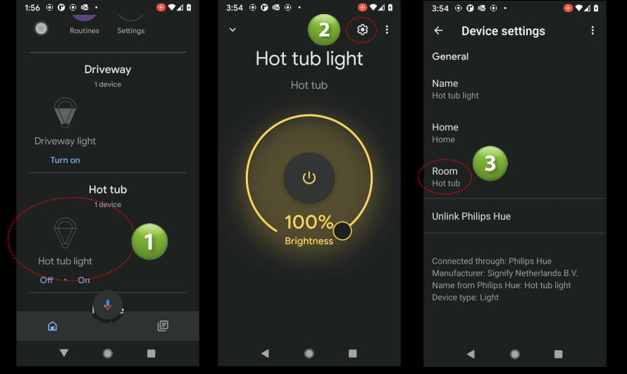
4. Choose or create a new room then hit the Save button. In our example we chose Living Room as the new room for the Hot tub light
5. Return to your Home screen to see that your device/light has changed rooms to Living Room.

Summary
In this article we showed you how to link Philips Hue to Google Home. We would love to hear what you have to say about this article so please leave a comment below. If you have any questions or need help you can post your question using the Ask Phil or the Community forums. If we don’t know the answer we will help find it.
Home Automation Protocols
Home Automation Protocols

In this article we will cover the many different communication protocols used in the Home Automation industry.
BLUETOOTH (Mesh)
Bluetooth is a low-power wireless technology that uses radio waves to transfer data between devices. Most of us know Bluetooth as the method we use to connect audio devices like speakers, head phones or cell phones. All of which use Bluetooth extensively.
Bluetooth Low-Energy technology (BLE) is used by many devices and Hubs in the Home Automation industry. This is a variant of the classic Bluetooth and is targeted at low power devices like the Internet of Things(IoT). It is different from the classic pairing version above in that it does not use pairing technology.
In 2017 Bluetooth Mesh profile was released which added the ability to perform a many-to-many style of communication with provisions for message relay from one device to another. This would create a flexible mesh topology with multiple potential paths between devices (nodes) to ensure delivery of messages. This means that data is relayed by transmitting data over the air (flooding) so that all devices in range can receive the transmission. Each device that then receives the transmission will use the unique sequence ID (included in every message) to determine it it needs to re-transmit (relay) the message Devices keep track of the sequence ID’s and do not relay if they have already seen or relayed the message. Messages also use a time-to-live counter (TTL) that gets decremented by one every time it gets relayed. The TTL is typically set to 3 and as it hops and reaches a value of 1 the device will no longer relay the message.
Bluetooth BLE is intended for devices that only need to transmit small amounts of data periodically, which can extend battery life by months or even years.
Thread
It is a low-power wireless mesh networking protocol based on the universally supported Internet Protocol (IP), and built using open and proven standards. A Thread network can self-heal meaning that if one of the devices in the network becomes inoperable the network can adjust and continue to operate. Thread is interoperable by design.
Devices in a Thread network are authenticated and communications are encrypted. Devices also use very little power and can operate on battery power for years.
A thread network will consist of Router and End Devices. A Router is a node that forwards packets for other devices and provides services for devices trying to join the network. A End Device is a node that communicates primarily with a single Router and does not forward packets for other network devices. It can also disable its transceiver to reduce power consumption. The relationship between a Thread Router and End Device is that of a Parent-child. A End Device will attach to only a single router. The Router is always the Parent while the End Device the child as a child.
Wi-Fi
Wi-Fi is wireless networking technology that uses radio waves to exchange data between a wireless router and Wi-Fi enable devices throughout your home. You may think that Wi-Fi is an acronym for something but it’s not. Wi-Fi is actually a brand name created by a marketing firm.
The IEEE 802.11 standard is what defines the protocols that allow communications between Wi-Fi enabled devices. There are multiple versions of this standard which include 802.11n (Wi-Fi 4), 802.11ac (Wi-Fi 5) and 802.11ax (Wi-Fi 6). There is even an extension to W-Fi 6 named Wi-Fi 6E that allows communication over a new frequency at 6GHz.
| IEEE Standard | Created | Maximum Speed | Frequency Band |
|---|---|---|---|
| Wi‑Fi 6E (802.11ax) | 2020 | 600 to 9608 Mbit/s | 6 GHz |
| Wi‑Fi 6 (802.11ax) | 2019 | 600 to 9608 Mbit/s | 2.4/5 GHz |
| Wi‑Fi 5 (802.11ac) | 2014 | 433 to 6933 Mbit/s | 5 GHz |
| Wi‑Fi 4 (802.11n) | 2008 | 72 to 600 Mbit/s | 2.4/5 GHz |
| (Wi-Fi 3)802.11g | 2003 | 6 to 54 Mbit/s | 2.4 GHz |
| (Wi-Fi 2) 802.11a | 1999 | 6 to 54 Mbit/s | 5 GHz |
| (Wi-Fi 1)802.11b | 1999 | 1 to 11 Mbit/s | 2.4 GHz |
| (Wi-Fi 0)802.11 | 1997 | 1 to 2 Mbit/s | 2.4 GHz |
Wi-Fi is the most recognized of the protocols/standards because it used by so many products and devices purchased by the general public. Almost every home has a W-Fi router installed which makes connecting Wi-Fi based Home Automation device a snap. In fact, Internet of Things (IoT) devices that utilize this protocol require no additional hardware or equipment. They basically just work out of the box.
Wi-Fi routers will typically use two different radio frequencies 2.4GHz and 5 GHz to communicate with Wi-Fi devices throughout your home. The 2.4GHz frequency has been around from the early days and is shared with many devices like cordless phones, microwaves, baby monitors, audio devices and more common devices used in a home. If you have a lot of these devices in your home you could experience overcrowded channels which will result in interference with your home automation devices. While many older home automation devices would work only on the 2.4Ghz frequency band newer devices will work on both 2.4 and 5 GHz.
While the 5 GHz band provides for faster data transfer speeds it has more trouble going through walls and obstacles in your home. This results in a shorter range (distance) which may cause intermittent disconnects of your devices if they are place too far from your router.
Zigbee
Zigbee is wireless mesh network protocol that targets battery-powered devices in a home automation system. It is based on the IEEE’s 802.15.4 network standard. Zigbee has been used in the home automation industry for more than a decade for low-powered devices that don’t require a lot of bandwidth – like your smart home sensors.
A mesh network is a local network topology in which the nodes (devices, bridges, etc.) communicate with other nodes to efficiently route data to clients. There is no dependency on any specific node which allows very node to participate in the relay of data. This means that each wireless node can communicate with each other and share data across a large area. Zigbee’s ability to utilize mesh networking means it can increase transmission range and provide greater reliability using self-healing algorithms.
For example, in a Zigbee based network you could have a master coordinator node that controls other network nodes. If one node fails for any reason and can no longer communicate with a second node, the master node and second node may re-establish communications by linking to a third node that is within range. In a mesh network every node acts as a repeater of sorts, and all nodes cooperate in the distribution of data – hence mesh network.
Zigbee operates in the 2.4GHz band and can support up to 65,000 nodes on a single network.
Z-Wave
Z-Wave is a wireless communication protocol used mostly in home automation systems to allow devices to communicate with each other. It is also based on mesh technology allowing each device to act as a repeater to provide a self-healing reliable network.
There are 1000’s of home automation products that utilize the Z-Wave protocol which allows for integration between many different manufacturers products. Z-Wave has one of the broadest product selections available.
Z-Wave uses a source-routed mesh network architecture. In this type of network devices send data/messages (initiator) which are then relayed by neighboring devices. Devices can communicate to each other by using other nodes to dynamically route around and circumvent obstacles or radio dead spots that might occur in a typical home. For example, data/messages from node A to node C can be successfully delivered even if the two nodes are not within range by using a third node B which can communicate with bot nodes A and C. If the preferred route is unavailable, the message originator will attempt other routes until a path is found to the C node. This means that a Z-Wave network can reach much farther than the radio range of a single node.
Z-Wave operates at 868.42 MHz in Europe, at 908.42 MHz in North America which avoids interference with systems that operate on the crowded 2.4GHz band. To provide security Z-Wave uses AES-128 encryption.
IP Protocol Over Ethernet
Ethernet is a wired networking technology used in Local Area Networks (LAN) and Wide Area Networks (WAN). It is also considered one of the key technologies that make up the Internet. Data is transferred over a physical cable as apposed to Wi-Fi that uses wireless technologies to send over the air. When it comes to Ethernet vs Wi-Fi speed, Ethernet is almost always lower latency (less delay), and higher bandwidth (more capacity) than Wi-Fi.
Cables for a Ethernet network are almost always classified as Cat 5e, Cat 6e or similar. The Cat stands for Category. The number that follows refers to the specification version supported by the cable. Generally a higher number means higher frequencies and therefore faster speeds.
| Category | Shielding | Max Transmission Speeds | Max Bandwidth |
|---|---|---|---|
| Cat 5 | Unshielded | 10-100Mbps | 100MHz |
| Cat 5e | Unshielded | 1,000Mbps to 1Gbps | 100MHz |
| Cat 6 | Shielded or unshielded | 10Gbps up to 55 meters | 250MHz |
| Cat 6a | Shielded | 10Gbps up to 55 meters | 500MHz |
| Cat 7 | Shielded | 100Gbps up to 15 meters | 600MHz |
| Cat 7a | Shielded | 100Gbps up to 15 meters | 1,000MHz |
| Cat 8 | Shielded | 40Gbps up to 30 meters | 2,000MHz |
Note: Maximum distance of an ethernet cable is 100 Meters or 328 Feet
There are many Home automation devices that use the Ethernet (TCP/UDP/IP protocol) over Ethernet. Some examples are IP Cameras, Hubs, Bridges, Televisions, Media devices and many more.
A Ethernet network can also supply power to devices using using Power Over Ethernet (POE) . This is accomplished by sending power over a pair of wires in the Ethernet cable from the POE enabled router. This can eliminate additional cabling thereby reducing overall time and costs.
Comparison
| Specification | Ethernet | Wi-Fi | Zigbee | Z-Wave | Bluetooth | Thread |
|---|---|---|---|---|---|---|
| Technology | Physical Wire | Radio Frequency | Radio Frequency | Radio Frequency | Radio Frequency | Radio Frequency |
| IP Based | Yes | Yes | No | No | No | YesIPv6 |
| Frequency | N/A | 2.4GHz & 5GHz | 915 MHz or 2.4GHz | EU 868MHzUS 908MHzAU 921MHz | 2.4GHz | 2.4GHz |
| Mesh Capable | N/A | No* | Yes | Yes | Yes | Yes |
| Mesh Hops | N/A | N/A | Unlimited | 4 | Unlimited(TTL based) | Multiple |
| Max Devices | 253** | 250 | 65k | 232 | 32,767 | 250 |
| Battery Power Consumption | N/A | High | Very Low | Very Low | Very Low | Very Low |
| Max. Range (indoor theoretical) | 100m 328' | 45m 150' | 10m35' | 30m100' | 100m 330' | 100m 330' |
| Theoretical Max Speed | 10,000 Mbps | 700 Mbps | 250kbps | 9.6-100 kbps | 2 Mbit/s | 250 kbps |
| IEEE Standard | IEEE 802.3 | 802.11a/b/g/n/ac/ax | 802.15.4 | 802.15.4 | 802.15.1 | 802.15.4 |
*Devices do not support Mesh (do not communicate with each other). Wi-fi can support Mesh networks
**Based on a typical home network. Actual number will depend on network configuration.
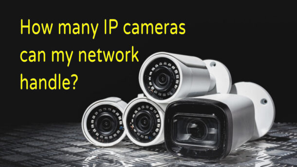
How many IP cameras can my network handle
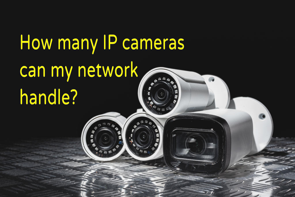
When it comes to figuring out how many IP cameras can work on your network, there are many factors that need to be considered. The most important is your available Bandwidth. In this article we will take you through each determining factor that will ultimately determine the number of cameras your network can handle. If you are interested in learning the why’s and how’s then read on. If you just want the calculator then jump right to our Calculator section at the end of this article to get your answer. ,
Network Bandwidth
So what is Bandwidth? Basically its the amount of data that can be sent over your network in a measured amount of time. To help explain let’s use pipes and water as an analogy.
Picture two different water pipes that are feeding a large bucket. The larger water pipe will allow much more water to flow through in a given amount of time. The smaller pipe will pass much less water in the same time period. In a network the water would be data and the pipes would be your network. So the more bandwidth your network has the more devices like IP cameras it can handle.
The amount of network bandwidth you have for your cameras will depend on your router, whether you are using Wi-Fi or hardwired network cables, type of camera equipment, configurations and what other devices are using your network. Wow you say. How do I ever figure this out. Well just read on and we help make sense of it.
One point we need to clarify is that your available network bandwidth is not the same as what was given to you by your Internet Service Provider (ISP). The speed of your Internet connection has no bearing on your internal network bandwidth/speed. It will come into play if you plan on viewing or storing video outside of your network. We will touch on that later in this article.
Before we get started I just want to cover the way we measure bandwidth so that we are all on the same page. Mbps stands for Megabits (1,000,000) bits per second. Notice the lowercase “b” as this is important. A lower case “b” refers to Bits while an uppercase “B” refers to Bytes (a group of 8 bits). So MBps is not the same as Mbps. Also we will be using Gbps in some cases which is Giga (1,000,000,000) bits per second. In this article we will be using Mbps or Gbps to describe bandwidth.

Routers and Switches
These days the consumer routers and switches are one in the same. In other words the switch is built into your router. If you have multiple port connections on your router than you can safely say that you also have a network switch.
So how do you figure out your specific bandwidth availability? You can start by checking the specifications of your router as this would be one of the main determining factors. Here are some items that will help determine your network bandwidth.
Wi-Fi 2.4GHz or 5GHz or the new Wi-Fi6
There are many different types of routers out there. Older routers are typically single-band that only handle the 2.4GHz signals (frequency). More modern routers are know as Dual-Band and can handle both 2.4GHz and 5Ghz. So why do I care? Well firstly, a 2.4GHz router has a limited bandwidth of approx. 600 Mbps (in ideal conditions) as compared to 1300 Mbps with 5GHz router. So if you have a single band 2.4GHz router then right of the bat you have a total bandwidth limit of only 600 Mbps (if using Wi-Fi for your cameras).
Another point to consider is that 2.5GHz is known to be more vulnerable to external interference which may also affect your IP Cameras connections. It’s a pretty crowded band. There are a lot of devices that use 2.4G such cordless phones, baby monitors, Bluetooth devices and even microwave ovens. On the over hand, 2.4G has a longer range (passes through walls better) than 5G so cameras could work at a greater distance. However, the 5G band is much less congested which means you are more likely to get a more stable connection. In most cases the 5Ghz band would be better for your IP cameras.
Now one more item that could affect your bandwidth are the 802 standards. Routers conform to specific standards and some standards provide better speeds. Therefore depending which standards your router supports will also determine its bandwidth. I hear ya…does it ever end? Don’t worry, we try to take out all this complexity with our easy to use calculator at the end of this article so don’t bail on us yet. Keep in mind that the cameras used also need to support the 802 standard(s) used by your router.
Now the latest and greatest Wi-Fi6 standard provides much faster speeds and higher bandwidth. It’s a game changer when it comes to bandwidth and overall capacity.
If you are still using a single-band 2.4GHz router then it might be time to look at upgrading to a 2.4G/5G dual-band router or even better a router that supports the new Wi-Fi 6/802.11ax standard.
IEEE Standards and their expected speeds
If you are the curious type the following chart provides some data on the 802 standards
| Name | IEEE Standard | Release Date | Band/Freqeuncy (GHz) | Expected Speed | MIMO | Coverage/Range |
| N/A | 802.11 | 1997 | 2.4 | 2 Mbps | Indoors: 20 m Outdoors: 100 m |
|
| Wi-Fi 1 | 802.11a | 1999 | 5 | 54 Mbps | Indoors: 35 m Outdoors: 120/5000 m |
|
| Wi-Fi 2 | 802.11b | 1999 | 2.4 | 11 Mbps | Indoors: 35 m Outdoors: 120 m |
|
| Wi-Fi 3 | 802.11g | 2003 | 2.4 | 54 Mbps | Indoors: 38 m Outdoors: 140 m |
|
| Wi-Fi 4 | 802.11n | 2009 | 2.4/5 | 300 Mbps | MIMO | Indoors: 70 m Outdoors: 250 m |
| Wi-Fi 5 | 802.11ac | 2013 | 2.4/5 | 866Mbps | MU-MIMO | Indoors: 35 m |
| Wi-Fi 6 | 802.11ax | 2019 | 2.4/5 GHz | 450 Mbps/10.53 Gbps | MU-MIMO | TBD |
Wi-Fi or Ethernet
The way in which you are planning to connect your network IP cameras will also affect your available bandwidth. As we mention in the previous section Wi-Fi bandwidth is limited by the router’s radio capabilities (router hardware and 802 standards). However, using hardwired Ethernet cable connections (network cables from your camera directly to your router/switch) will provide better overall performance as the speed/bandwidth for network cabling is much higher than Wi-Fi. Also, let’s consider that the Wi-Fi bandwidth that we listed above in the 802 standards is for all cameras connected to that same router. It is shared between all of the cameras. With Ethernet cables cameras are not sharing their connection to the router/switch. With the right Ethernet cables and router you can theoretically reach up to 10Gbs.
Connecting your cameras with Ethernet cables is certainly a better method for connecting your cameras but it comes with some additional difficulties. Most home/small business owners don’t have the skill nor the ambition to run cables throughout the home/business. Fishing walls, crawling in attics, crawling in crawl spaces, making holes, etc. are just not the things most want to do. However, for those with the skills and drive it would certainly pay off in the end if all your cameras were connected by network cables. Don’t get me wrong, if you have a good Wi-Fi network, the correct amount of cameras properly configured then Wi-Fi will work just fine.
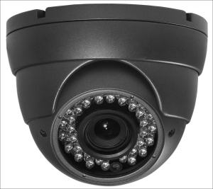
Cameras
There are many different camera types and configurations which can have a huge effect on bandwidth usage and thereby the number of IP cameras you could support on your network. We will go through how different cameras and their configuration can effect your bandwidth.
Resolution
Resolution is referring to the number of pixels being captured by the camera’s image sensor. The data from these image sensors are then compressed and streamed (transmitted) over the network. So a 2 Megapixel (MP) camera would send half the amount of data of a 4MP which in turn will send half of a 8MP camera. As you can see that higher resolution cameras would eat up your bandwidth quickly if you had a lot of them.
| Typical IP Camera Bandwidth | ||
| Resolution | H.264 | MJPEG |
| 1MP (1280*720) | 2 Mbps per camera | 6 Mbps per camera |
| 2MP (1920*1080) | 4 Mbps per camera | 12 Mbps per camera |
| 4MP (2560*1440) | 8 Mbps per camera | 24 Mbps per camera |
Frames per Second (FPS)
Cameras can be configured at different frame rates which will effect your bandwidth usage. For example, a camera set to 1 FPS would be capturing 1 image (frame) per second. This image would then be compressed and sent over the network using a certain amount of bandwidth. Now if we were to set the same camera to 10 FPS with all other factors remaining the same we would see a increase in our overall bandwidth requirements. You may think that since we increased our frame rate by a factor of 10 that our bandwidth would also increased by a factor of 10. Well this wouldn’t be the case as frame rates do not have a linear affect on bandwidth. This is due to compression codecs like H.264/5 and how they work. Suffice to say that you will realize a bandwidth increase in our example but it may be somewhere between 3-4x not 10x as expected.
Setting the correct frame rate is important and the frame rate you choose will depend on your particular needs for the given camera. A typical rate used in the industry is 15 FPS which provides the best compromise between details being captured and bandwidth used.
Video Compression
Video data from IP security cameras is always compressed before sending over a network. The most common compression standard used in the security industry today is H.264. Depending on which video compression codec (encoder/decoder) is used by your camera it will have an effect on the overall bandwidth usage on your network. However, most security cameras today support and default to the H.264 standard.
The newer H.265 codec is also available and has higher compression rates. It could improve your compression by up to 50%. However, it isn’t as widely adopted yet and may have a higher chance on incompatibility with some hardware.
Standards such as MJPEG is also available in many cameras. This standard provides high quality video and uses less processing power that H.264/5 but uses much more bandwidth and storage space. So if you have a choice we would recommend using H.264/5

How you use your cameras will affect your Bandwidth usage.
The way in which you plan to use your cameras will also affect your bandwidth.
Viewing
If you are not storing video somewhere on the network (see next section) and nobody is viewing any of your cameras then your cameras will be using almost no bandwidth at all. They would be only sending very small amounts of data just for housekeeping reasons. Its only when you request to view any video that your camera(s) will start sending their video data and using your available bandwidth.
Storage
Video storage is the process of retrieving video from your IP cameras and placing it on a storage media device for later viewing. In a home or small business environment this is typically done by storing locally in the camera on a SD card or on a Network Video Recorder (NVR).
Storing locally on a SD card means that the video will not be sent over the network, thereby reducing bandwidth usage, but is stored locally on a small SD memory card inserted into the camera. This comes with some great benefits but also some drawbacks like limited storage capacity. Not all cameras have the local storage feature but many do.
Storing video on a Network Video Recorder (NVR) has its own pros and cons but the main drawback is that may use your network bandwidth continuously. So depending on the frame rates, compression, resolution and other configuration options are set on your cameras there could be large bandwidth usage. This would be compounded if you have multiple cameras on the network.
Of course you also have the option of not recoding video at all and relying on features like video motion detection to have video clips sent to your phone.

| Feature | Local SD Card | NVR |
|---|---|---|
| Bandwidth Usage | Low | med-high |
| Storage Capacity | Low - typically 128G max | High |
| User Experience | Med | High |
| Cost | Low | High |
Video Storage
Camera resolution is probably the biggest factor on bandwidth usage. Resolution is referring to the number of pixels being captured by the camera’s image sensor. The data from these image sensors are then compressed and streamed (transmitted) over the network. So a 2MP camera would roughly send half the amount of data of a 4MP which in turn will send half of a 8MP camera. As you can see that higher resolution cameras would eat up your bandwidth quickly if you had a lot of them.
Summary
So now that we have covered the main factors that affect your bandwidth usage we can start planning or camera system to both meet our needs but keeping within our bandwidth availability.
Bandwidth Calculator
RESULTS
| Bandwidth Storage: | 0 mbps |
|---|---|
| Bandwidth Local Viewing: | 0 mbps |
| Bandwidth External Viewing: | 0 mbps |
| Total Bandwidth: | 0 mbps |
Camera Type 1

Camera Type 2

Camera Type 3

Camera Type 4

Router

NVR
![]()

Remote View

Local View

Philips Hue Outside Motion Install
How to Install Philips Hue Outdoor Motion Detector
In this article we will be covering the installation of the Philips Outdoor Motion detector. To use this sensor, you will need a Philips Hue Bridge (Gen 2) and a Hue lamp. By connecting the sensor to your bridge via the Philips Hue app, you can select which lights go on, even inside your home. You can also choose the scene or light setting that should be activated. The integrated dusk-to-dawn sensor makes sure your lights only switch on when it is actually dark outside helping you to conserve energy.
What you get
You will get everything you need to install this sensor in a multitude of locations. It comes with a very ingenious base/bracket that allows you to mount flat on a wall, in a inside corner or outside corner

Motion detector. High quality construction . Comes with batteries inside
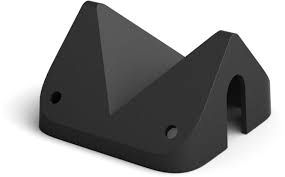
Corner mount. Can be used to mount detector on inside or outside corner.
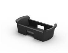
Wall mount. Used to mount on a flat surface or to pipes/down spouts using a cable tie.

Very detailed user’s manual.
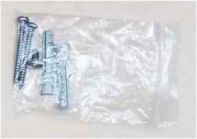
Package of wall anchors and screws for mounting.
Step 1- Add Outdoor Sensor to Philips Hue App
The first thing we need to do is to add your new sensor to the Philips Hue App.
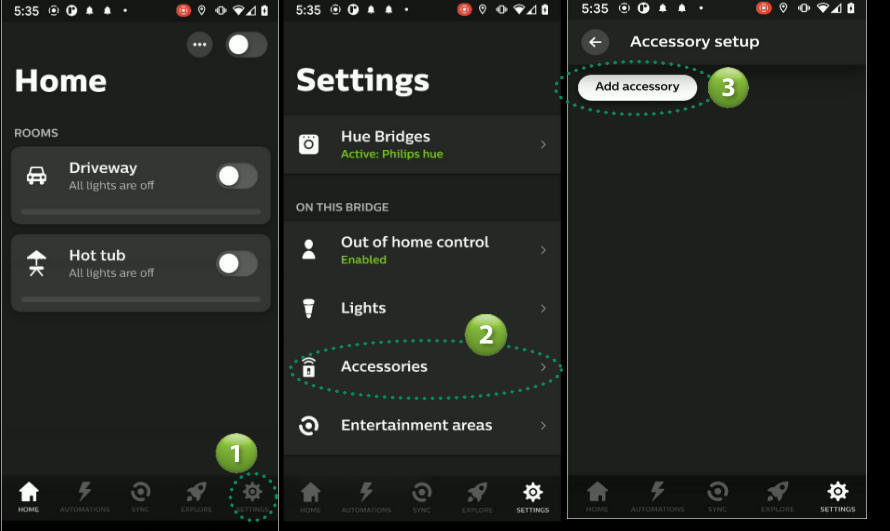
- Open the Philips Hue App. From the Home screen select Settings from the menu at the bottom.
- Select the Accessories option from the Settings menu.
- Select Add accessory button.
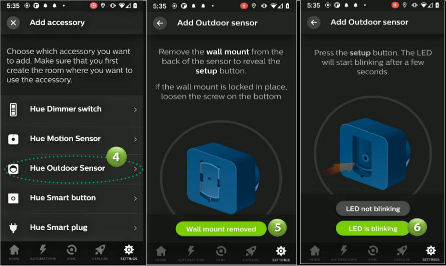
- Select the Hue Outdoor Sensor
- Remove wall mount from the back of the sensor to reveal the Setup button. Select the Wall mount removed button
- The sensor lens (white portion on front) should now be flashing red to signify it’s ready to be found. Select the LED is blinking button.
- The App will now search for the Outdoor Sensor and will display a Success screen when found. Select the Continue button.
- Select the room you would like this sensor to be added to. In our example we will be adding to our room named Driveway
- At this point your outdoor sensor has been added to the Philips Hue App but has been configured using default settings. If the default setup meets your needs, then select the Done button to complete the setup. If not, then check out the next section for help on configuring the sensor to meet your needs

Step 2 - Configuring the Hue Outdoor Sensor
In this section we will look at the many options you have for configuring your sensor.
- Go to the sensor settings screen by selecting the Change Settings button as shown above. If you are no longer on that screen, then you can select Accessories from Home screen then the name of your sensor.
- The sensor’s settings screen will be displayed. First change the name of your sensor to something that makes sense for you. In our case we will name the sensor “Driveway Motion”.
- Next we need to set the sensor’s behavior during the day. Start by selecting the Between option under the DAY BEHAVIOR section. Here you can specify when the Day period begins by selecting a time (hour and minutes). In our example we will select 8:00am. Select SET when done. Don’t worry about the End time as we will set that from the NIGHT BEHAVIOR section later.

- We now need to tell the sensor what we want it to do during the Day time hours as defined above. From the Settings screen select the Room (in our case we used Driveway, yours may be different).
- Select the scene you want the motion to activate during the Day. In our case we don’t want anything to happen so we will select Do nothing.
- In the After section we can specify what happens after it has tripped during the day. First we need to specify how much time to wait before activating our action. It defaults to 10 minutes but you can change this from 1 to 60 minutes. You can do this by selecting the After option then selecting a time from 1 to 60 minutes. In our example we are not doing anything during the day so we will skip this setting and leave as is. Of course, if you have activated an event/scene above then go ahead and set an After Time.
- While still in the After section, we need to specify what is to happen when a sensor resets and the time expires from step 6 above. Since we have selected to Do nothing during the day we don’t need to worry about doing anything so we will leave this at the default of Do nothing. Again, if you specified some action in step 5 above then you can select what you want to happen After the trip and the After time expires. For example, if you specified that a Bright scene should be activated during the day in step 5 then you could set the After action here to Off or Return to previous state.
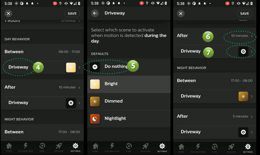
- We now need to setup the NIGHT BEHAVIOR for our sensor. In our example we are installing the outdoor sensor to turn on a front door light and we will want the light to turn on between the hours of 5pm and 8am. We do this by setting the Between time.
- We then select what we want to happen by selecting an action from the Driveway room (this could be a different name in your case). Select the Driveway room
- Select an action that you want to happen when the sensor is tripped. In our case we will activate the Driveway light Bright scene.
- Next we need to set the After action for sensor trips that occur during the night between time. Start with the After time. We have set to 5 minutes. This means that 5 minutes after a sensor is tripped the action you specify in step 12 below will be activated.
- In the Driveway room (your name may differ) select an action that you want to occur once the time expires (step 11). In our case we have selected Return to previous state which will set the light to the state it was prior to the motion being activated.
- Finally select Save to save all your changes.

Step 3 - Hue Outdoor Sensor Advanced Settings
In this section we will take a look at the Advanced Settings Daylight sensitivity and Motion sensitivity.
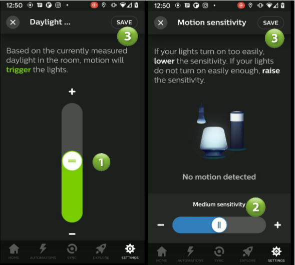
- Select the Daylight sensitivity option under ADVANCED SETTINGS. This is a very important setting and if set incorrectly I believe is the cause of some users thinking that the sensor is defective. Basically what this setting does is determine when the sensor will trigger events based on the current light levels surrounding the sensor. You adjust this by sliding the slider button up and down until you see it turn Green and the text states “trigger”. If the slider turns Orange and the text above states “not trigger” then no matter what happens at the sensor you will not get it to trigger and therefore it may look like the sensor is not working. However, this is not the case and it’s just that at the selected light level it has been told not to activate. Now the other item you need to watch for is when you set this light level. For example, if it is sunny outside and you set this level then the sensor will never trip at night because you told it it needs bright sunshine before activating. Vise versa if you set this level when it’s pitch black outside (around the sensor) then the sensor would be allowed to trip essentially all the time. So to set this level properly we would need to adjust it when the light level outside is at a level that we want our sensor to start tripping. For dusk levels the slider would typically be at approx. 50%.
- To adjust how sensitive the sensor should be select the Motion sensitivity option. If your lights are turning on too easily then lower the sensitivity here. If you lights are not turning on when there is movement in its field of view, then increase the sensitivity here. This screen is also dynamic meaning it shows you when the motion is being tripped in real time.
- Make sure you select Save to save your changes
Step 4 - Installing the Outdoor Sensor
Sensor Placement
To install your sensor we first need to select the best location to provide the coverage you need for your specific application. The sensor should be mounted between 1.5m and 2.5m (59″ and 98″) above the ground. At the 2.5m (98″) height the sensor will detect up to approx. 12m (40′) out from its location. Lowering its height to 1.5 m (59″) will shorten the range to approx. 9m (30′).


This uses PIR (Passive Infrared) technology which has a specific detection pattern as shown below. When planning your location keep in mind that the best detection direction is across the fingers as apposed towards/away motion. Try to place the sensor so that the expected direction of travel would be across the pattern as shown.

Mounting the Sensor
The sensor can be mounted flat on a wall, on an outside corner, inside corner or on items such as down spouts.
On a Flat Surface/Wall

Using the wall mount, fasten it to the surface using the supplied screws and if needed anchors. Place the Sensor over the Wall mount and then tighten the Lock screw. Make sure the sensor is sitting flat on the surface.
On Outside Corner

Fasten the Corner Bracket to the wall using one 3.5cm (1 3/8″) screw. Attach the Wall Bracket using the supplied machine screw. Place sensor over Wall Bracket and tighten the Lock screw. Make sure the sensor is flush to the Corner bracket.
On Inside Corner

Using the wall mount fasten it to the surface using the supplied screws and if needed anchors. Fasten Wall bracket to Corner Bracket using the supplied machine screw. Place the Sensor over the Wall mount and then tighten the Lock screw. Make sure the sensor is sitting flat on the surface.
On Down Spout/Pipe

Using the wall mount, fasten it to the sensor and tighten the Lock screw. Feed a cable tie through the openings on the side of the Wall Bracket and extend around the pipe or down spout. Tighten tie to securely mount the sensor.
Changing Hue Outdoor Sensor Batteries
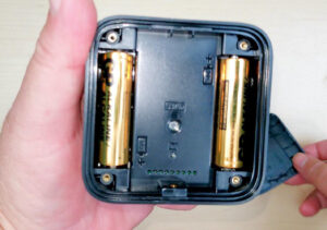
There will come a time when you will need to replace the batteries inside the sensor. This can be done by first removing the sensor from the Wall mount. Next unscrew the 4 Philips screws on the rear of the sensor. Do not remove them entirely. Remove the Lock screw. Pull on the screws to separate the back plate from the sensor. If you can’t remove the plate then unscrew the 4 screws until it releases.
There are two AA batteries inside the sensor. Replace with the new batteries and screw the back plate back on to the sensor. Replace the Lock screw.
Specifications
| Manufacturer | Signify Canada Ltd (Philips) |
|---|---|
| Part Number | 541730 |
| Product Dimensions | 7.59 x 5.59 x 7.59 cm; 145.15 Grams |
| Batteries | 2 x AA Batteries |
| Item model number | 541730 |
| Colour | Black & White |
| Style | Outdoor Motion Sensor |
| Voltage | 3 Volts |
| Item Package Quantity | 1 |
| Batteries Included? | Yes |
| Warranty Description | 2 Year Warranty |
| Item Weight | 145 g |
Products Included in this Article
Other products you may be Interested in
- Philips Hue White LED Smart Button Starter KitPhilips Hue White Ambiance Smart Bulb Starter KitPhilips Hue 552349-2 Smart Plug, 2 Count (Pack of 1), WhiteAMAZON ONELINK IMAGEAMAZON ONELINK TEXT
How to Install the Skylink SK-200 Alarm System
Skylink SK-200 Alarm System Installation
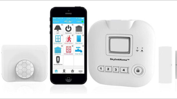
In this article we will be covering the installation of the Skylink SK-200 Alarm Starter Kit. The SK-200 alarm and automation starter kit provides you with the basics needed for a do-it-yourself alarm security. The included Hub connects to your local network and provides easy cloud based remote control and notifications through the Internet. Why is this system perfect for a DIY project? Well there are no set-up or monthly fees. You use the iOS or Android app to monitor and control your system from almost anywhere. Push notifications can be sent to your smartphone whenever an alarm is activated.
What you get
The SK-200 is a starter kit so you only get the devices for a small home or apartment but you can easily add more sensors to expand your system as needed.
Kit includes one (1) Hub. This is basically the brains of the system which communicates with the other devices in your home. It connects to the Internet through your existing Internet router to send notifications to your phone and receives commands (arm/disarm). Requires 4 AAA batteries. (Batteries not included).
Kit includes one (1) Keychain Remote with 4 buttons. Arm Away, Arm Home, Disarm and Panic. You can purchase additional Remotes as needed.
Kit includes one (1) Passive Infrared Receiver (PIR) Motion Detector. This detector can be placed on a table or mounted on a wall and will detect movement within its field of view. Again, you can purchase additional detectors if/when needed. Requires a single AA battery (Batteries not included).
Kit includes two (2) WD-MT Wireless Door/Window sensors. Requires one (1) AAA battery (Batteries not included).
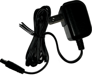
One (1) Power Adapter (6v .5 amp) for the Hub. Comes with 6′ cable

One 6′ Ethernet Network Cable for connecting the Hub to your existing router.
Two (2) Skylink decals.
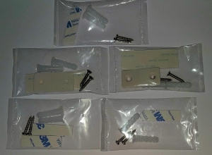
Multiple screws, wall anchors, 3M double sided tape and spacers for the motion detector.
Step 1- Hub Installation & Power Up
The first thing we need to do is setup the Alarm System Hub. The Hub needs to be placed/mounted within 6 feet of your Internet router. This will allow you to connect the Hub using the supplied 6′ Ethernet network cable. If needed, you could order a longer network cable if the Hub needs to be mounted further than 6′. I have included a link to a longer network cable in the Product section at the end of this article.
Connect the Hub to an available network port on your router with the supplied network cable. Then plug in the power adapter to both the Hub and wall outlet. At this point the small network LED should show green. If Red then there is a network connection issue.


Next open the rear compartment on the Hub and insert 4 AAA batteries. These batteries are optional but will keep your Hub operational during a power power outage and is highly recommended.

Step 2 - Download & Install SkylinkNet App
With your Android or Apple smart phone, go to your App store. For Android, this would be the Google Play Store while Apple would be the Apple App Store. These store App’s should already be somewhere on your phone.
1. Once in the store search for the “SkylinkNet” App.
2. Make sure you choose the correct App. The icon has a house with a blue background.
3. Next, select Install.
4. When installed, select the Open button to start the App. Alternatively, you can close the installation screen, find the new icon for the SkylinkNet App and open from there.

Step 3- Create an Account
1. You should now have the Logon screen showing on your phone. If you don’t already have an existing account with Skylink then select the “Create Account” link at the bottom of the screen. Otherwise Login with you existing credentials.
2. Read the Terms & Conditions then select the “I accept” checkbox.
3. Select “Continue”
4. Fill in your Name, Email and Password
5. Select the “Sign Up” link to register

You should now receive an email with a link. Click the link to complete the sign up process and activate your account. Once you click the link you should be brought to a web page confirming you have successfully setup your account.

Step 4- Setup Hub
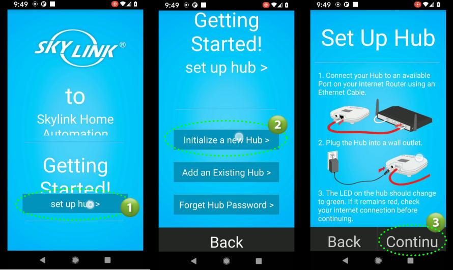
1. The Getting Started screen should be displayed in the SkylinkNet App. Select the “Setup Hub” link.
2. Select “Initialize a new Hub” button
3. A confirmation screen will be displayed confirming that you have installed the Hub and that it is powered up. This was done in Step 1 above so click the “Continue” link.
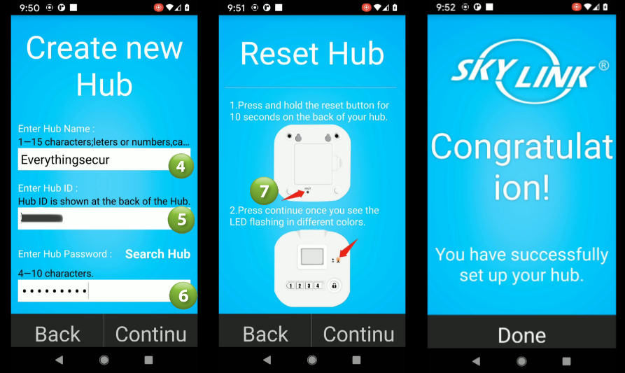
4. The Create new Hub screen will be displayed. Enter a name for your Hub. This name will show throughout the app and describes your Hub. For example, if you only have one hub and it’s in your home then I would recommend “Home” as the name.
5. Look at the bottom of your Hub for its Hub ID number and enter into the Hub ID field.
6. Enter a Password. This is not the code for the alarm. It’s used whenever the App/Server needs to communicate with the Hub.
7. Using a small screw driver or paper clip press and hold the Reset button on the bottom of your Hub. The LED should start flashing in multiple colors. This will initialize communications with your App. The Congratulations screen should now be displayed indicating successful connection to your App. Select “Done” to go to your Home screen.
Step 5 - Power Up Sensors
Before we can learn or enroll our sensors, we will need to first power them up.
For each Door Sensor open the cover by pressing on both sides of the cover (tabs) and pulling. Insert a AAA battery. The red LED should flash when you insert the battery.
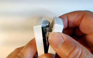
Do the same for the Motion Detector. To open you can use a coin or a flat head screw driver. Again, the LED should flash indicating it is transmitting to the Hub when the battery is inserted. Motion Sensors take a AA battery.

Step 6 - Enroll Door Sensors
We now need to tell the system what Door Sensors you will be installing. The App should be on the Home screen from Step 4 above.
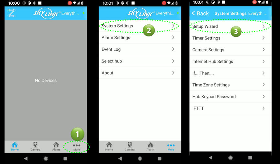
1. From your Home screen select “More” (three dots) to show the Setup Menu.
2. From the menu select “System Settings“
3. Select “Setup Wizard” from the System Settings menu
4. Select “Add Device” from the Setup wizard menu
5. Select “Sensors” from the Add Device menu
6. Select “Door Sensor” from the Select Type menu

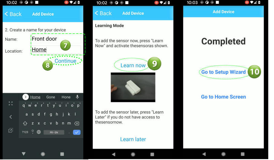
7. Enter a name for this door sensor (i.e. Front door) and a Location (i.e. Home). These two text descriptions will be used to describe the sensor on the App’s Home screen. You can use any combination of text that makes sense for you. So using the text in our example above the sensor icon would look like the icon shown to the right.
8. Select “Continue”
You should now be showing the Learning Mode screen. Before we start the enrolling make sure the sensor you are adding has it’s magnet placed next to the sensor as shown below

9. Select the “Learn now” link. The App will then try to connect to your Hub and learn a sensor. Activate (remove magnet away from sensor) your sensor. The red LED should flash indicating it has transmitted a signal to the Hub. At this time the Completed message should appear confirming that the sensor has been learned.
10. To enroll additional sensors select the “Go to Setup Wizard” link and repeat the above steps. When done with all door sensors select “Go to Home Screen“.
Step 7 - Enroll Motion Sensors
Adding Motion detectors is almost the same process as adding the Door Sensors above. The only difference will be selecting “Motion Sensor” from the Select Type menu.
You should now be at the Setup Wizard screen.
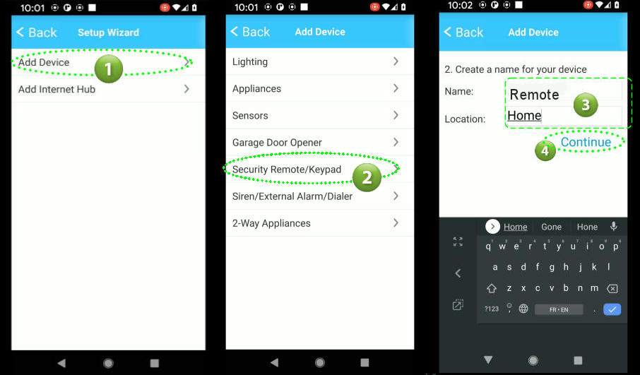
1. Select “Add Device“
2. Select “Sensors” from the Add Device menu
3. Select “Motion Sensor” from the Select Type menu

4. Enter a Name and Location
5. Select “Continue“
The Learning Mode screen will be displayed
6. Select the “Learn now” link to put the system into Learning mode. Push the Learn button located inside the motion detector.
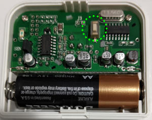
7. The Completed screen will be display to confirm that the motion detector was enrolled or learned. Select Go to Setup Wizard and then repeat the above steps if you have more sensors to enroll.

Step 8 - Enroll Remote Key fob
To enroll or learn a remote key fob follow the same process as adding a Motion Detector but instead you select “Security Remote/Keypad” from the Add Device menu.

Step 9 - Installing Door Sensors
There are two parts of a WD-MT Wireless Door Sensor. A Magnet (smaller piece) and a Sensor. The Magnet is typically installed on the door or window while the Sensor is installed on the unmoveable frame. However, depending on your particular door/window you can reverse this if needed. Choose the best orientation for your situation while ensuring the gap between the Magnet and the Sensor is no more than 10mm or 1/4″. Important: Make sure the small triangle markings on each piece is lined up and facing each other. To install, use the supplied double sided tape and firmly place each item on the door and frame. When done open the door/window to ensure the two pieces do not touch or rub. The Red LED should flash when you open the door/window. This signifies that a signal has been transmitted. Repeat these steps for all of your door/window sensors.


Step 10- Installing Wireless Motion Detector
Placement of your PS-MT Motion Detectors is important to ensure you get the best possible detection while avoiding false alarms. The following are some do’s and don’ts when mounting your detector.
Don’ts
- Don’t point a detector at a window. Sun light will trip a PIR sensor.
- Don’t install this sensor where pets could enter the field of view (FOV). There are special detectors intended for use with pets.
- Don’t point at a hot air source like vents, heaters, air ducts, refrigerators or stoves
- Don’t mount pointing at ceiling fans or curtains
- Don’t mount detectors in a high humidity area like bathrooms and attics
Do’s
- Do mount between 6-8 feet (182cm-243cm) high from the ground/floor.
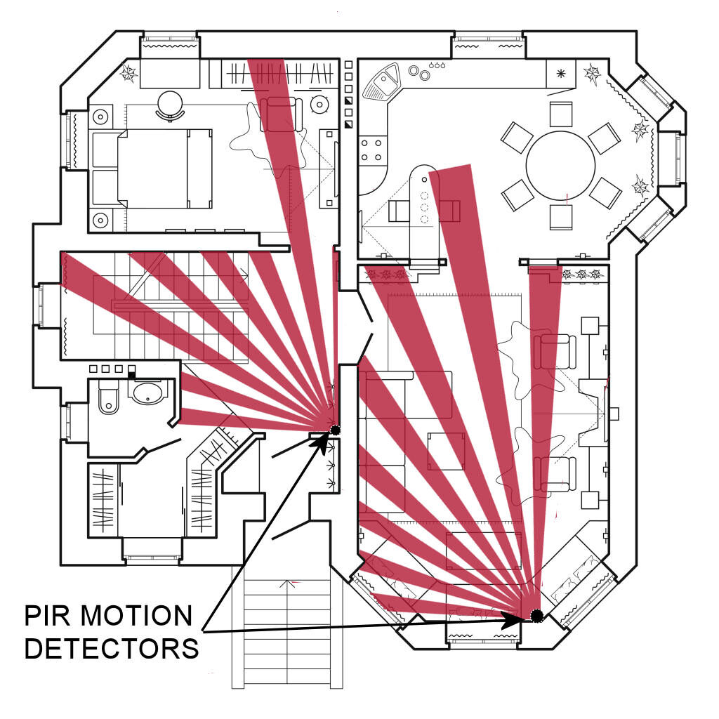
- Do mount sensor in a corner where possible. Corners tend to provide better coverage based on the pattern a detector senses.
- Expected direction of movement should be across the sensor rather than towards/away from sensor if possible. Always try to place sensors where you can take advantage of the cross motion direction.
- Motions placed in central hallways are always a good location as an intruder would typically use the hallway to access different areas.
Direction of Movement

Floor plan with PIR Motions
Mounting the Sensor
To mount a Wireless Motion Detector you can use the supplied double side tape or screws.
To mount on a wall with double sided tape simply apply the tape to the rear sensor and press firmly onto any wall surface.
Note: Removing double sided tape from a wall may damage your surface (remove paint or surface).
If using screws first separate the sensor by removing its back. You will see two indentations for the screws. You will notice that they don’t protrude all the through the sensor. One may be hidden behind a small piece of round foam. Using a Phillips head screwdriver (star) screw the sensor onto the wall through these indentations. You may want to pre-drill to make it easier but with adequate force and a good screwdriver you shouldn’t have any issues.
Corner mounting is a bit more difficult as there are no pre-drill holes or indentations in the sensor. You will need to drill some holes in the angled sides of the sensor back. Then use the screws (and anchors if needed) to mount the back plate of the sensor each wall.
Replace the front of the sensor and you are done.
Step 11 - Configuring the system to meet your needs
In this step we will configure your new system by setting the different options to meet your particular needs.
Setting your System Code (Hub Keypad)
The Hub has four (4) button keypad marked 1-4. These can be used to Arm and Disarm your system by entering an eight (8) digit code.
1. To set a code select the More (3 dots) at the bottom right of your Home screen.
2. Select “System Settings”
3. Select “Hub Keypad Password” from the System Settings menu.

4. In the Password field enter eight digit code. You can only use the digits 1,2,3 and 4. Any combination of those four digits will work.
5. When done select “Save“

To test your new code, enter it into the Hub keypad and press the Lock key. This should arm your system and start a count down timer (beeping). Enter your code again and press the Lock button to Disarm the system
You now have a code to Arm and Disarm your system from the Hub.
Setting your Time Zone
To operate properly the system needs to know which Time Zone you are in. To set your Time Zone:
1. To set the Time Zone select the More (3 dots) at the bottom right of your Home screen.
2. Select “System Settings”
3. Select “Time Zone Settings“

The App will set the Time Zone to what you already have configured in your phone.
4. If the default Time Zone is what you want then just select the Yes link
5. If you would like to choose a different Time Zone then you can do that here. Just select the correct time and the Time Zone will automatically be assigned.
6. Select “Save” to set the Time Zone

Alarm Timing Settings
The Alarm Settings screen allows you to set multiple system timing values.
Siren Duration:
This setting tells the system how long the siren should sound when an alarm is tripped. Select the duration on the right to change the value. Options are 0 (no siren), 1 min, 3 min, 5 min, and 10 min.
Entry delay:
The amount of time the system will delay or wait to activate an alarm when you trip a sensor that has been setup to have a delay. Options are 0 (no delay/instant), 30 sec, 45 sec, 60 sec and 75 sec. Typical setting is 30 secs. A slow pulsing beep will be heard when you trip an Entry sensor and speed up as it gets closer as it counts down to zero seconds. This allows you to enter your premise without tripping the alarm and disarm.
Exit delay:
The amount of time the system will delay arming your system. A slow pulsing beep will be heard during this delay and will speed up as it counts down to zero. This gives you time to exit your premise without tripping any sensors.
Beep Level:
The system will emit beeps to alert you of timer count downs, system armed and system disarmed. This setting allows you to control the volume. Options are Disabled, Normal, Low and high.
Step 12 - Sensor Setup
One of the last things we need to do is to set the Alarm Type for each sensor so that they react to the way you use the system. For example, you may want to have your motion sensors only be armed when you are out of the house (Away Mode). To make this happen you set the sensor Alarm Type to “Arm Away Only” which means this sensor would only be active when you are out of the house (Away). To be armed in the Home mode means that you are still in the house when the system is armed. The following are the different settings available that you can assign to your sensors.
| Alarm Type Setting | Armed Away | Armed Home | Disarmed | Delay on Exit | Delay on Entry |
|---|---|---|---|---|---|
| Arm Away Only | |||||
| Arm Home/Away | |||||
| Instant Alarm | |||||
| Disabled |
Setting your Alarm Type
1. If not already on your Home screen, select the Home Icon at the bottom of your screen. A screen with multiple icons should be displayed that match the number and type of sensors you enrolled in the previous steps.
2. Select the settings icon of the first sensor (in our case it’s the Front door sensor).
3. Select “Alarm Settings” button
4. In our case we will select this sensor’s Alarm Type to “Arm Away Only“. This would mean that this sensor can only trip the alarm if the system is set to the Armed Away mode. Select your Alarm Type by clicking on it in the list. The type will then be set and you will be returned to the Home screen.
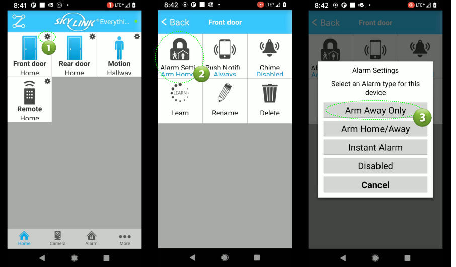
Repeat the steps 1-4 above to set the Alarm Type for each sensor in your system.
Setting up Push Notifcations
The system has the capability to send notifications to your smart device. This is called Push Notifications. Example of a notification would be an Door Opened message or Alarm tripped message.
You setup Push Notifications for each sensors and Remote in your system.
1. Go to your Home screen.
2. Select the settings icon of the first sensor (in our case its the Front door sensor).
3. Select “Push Notifications” button
4. Select During Alarm Only or Always depending your needs. If Alarm Only is selected then you will receive notifications from the sensor only when the system is armed Away or Away/Home. Typically you would select During Alarm to prevent continuous notifications when the door is opened/closed. Once you select you will be brought back to the Home screen. Repeat the above steps for each sensor and Remotes.
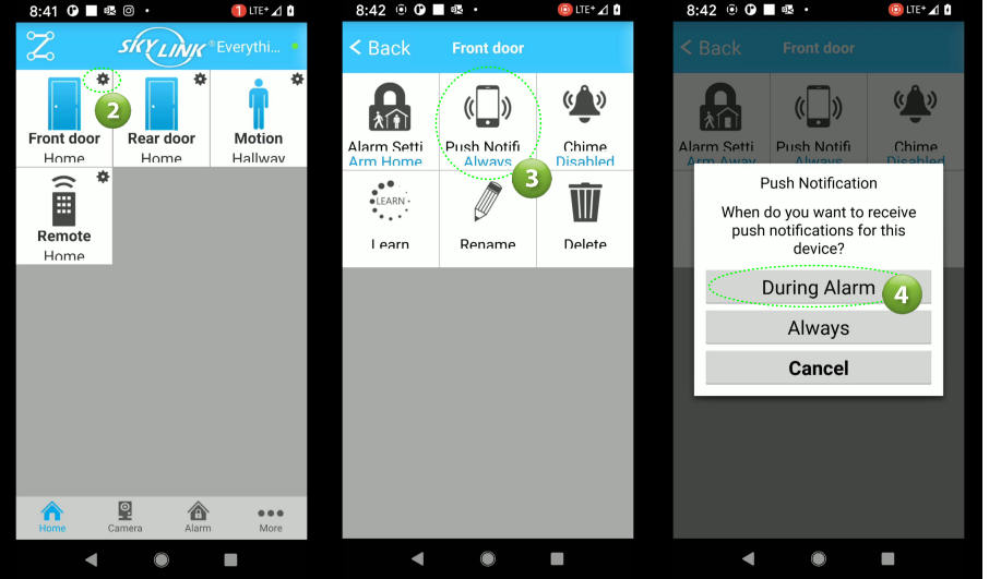
Setting up the Chime Feature
Every sensor can have a Chime assigned to it so that when the door/window is opened or a Motion is tripped you will get a Chime sound from the Hub. This is a fantastic feature and can be useful in many situations.
1. To setup a Chime for any sensor go to your Home screen and select a Sensor button.
2. Select the Chime button from the sensor screen
3. Select Yes to turn on the Chime or No to disable. You will be brought back to your Home screen. Repeat for each sensor you want to Chime.
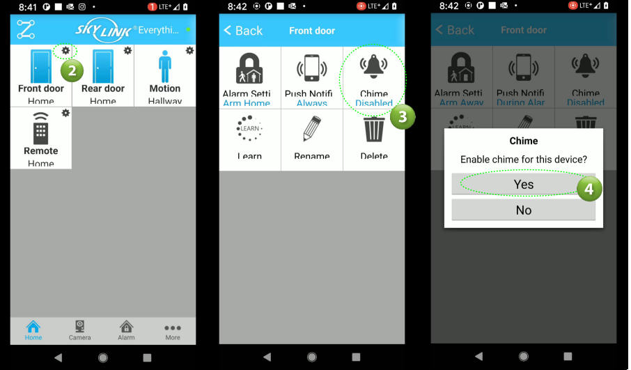
Step 13 - Testing your System
One of the most important steps when installing alarm systems is testing the system after the install. Even professional alarm technicians some times fail to perform proper and complete checks. It’s important to thoroughly check every device/feature to ensure they work as inspected.
To test your system you can use your phone App and walk the premise while tripping each sensor while putting the system in the different armed state (Disarmed, Armed Away or Armed Away/Home).
1. Start with the system disarmed and proceed to the first sensor.
2. Open the door/window or trip the motion detector. The red LED should flash on the sensor. Verify on the smart App that the intended result has occurred. Depending on the Alarm Type you may or may not receive an alarm trip. Only sensors set as Instant alarm types should cause an an alarm when the system is disarmed.
3. Next Arm the system and verify the Exit count down begins (beeping).
4. Open the door/window or trip the motion while in the exit count down. You should not receive an alarm.
5. After the count down as expired, open the door/window and the entry beeping should start. Once the entry delay expires you should receive an alarm. Verify the proper icon displays the alarm. Also, make sure the duration of the entry delay is adequate to allow you time to disarm the system (if using the Hub keypad).
Repeat the above 5 steps for each sensor installed while also verifying the proper zone/sensor icons are appearing on the App.
Next remove the Hub power adapter from the receptacle and ensure your system remains operational. You should be able to arm and disarm the system as normal. Replace the adapter and verify no change on your smart App.
You should now have a fully installed and tested system.
Step 14 - Using your New Wireless Alarm System
In this section we will cover the day to day use of your new alarm system. The different screens below can be opened by selecting the appropriate icon on the bottom of your screen.
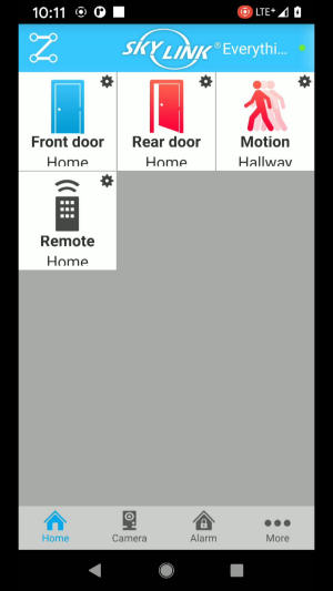
Home Screen
The Home screen is where you can quickly see the status of every sensor in your system. Each sensor will show a button with a icon depicting the type of sensor (Door, Motion, Remote etc.). These are real time status icons so they change as the sensor status changes. When a sensor is tripped or open it will show a red icon and a blue icon when its in normal state (closed/no motion detected).
Alarm Screen
The Alarm screen displays the current armed status of your system (Disarmed, Arm Home or Arm Away). You can also arm your system into any mode from this screen.
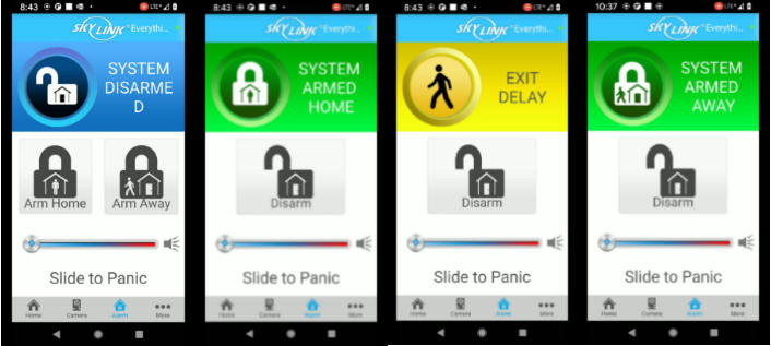
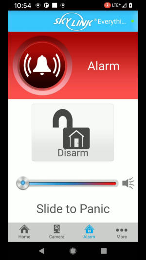
Panic
The Alarm screen displays also provides a Panic feature were you can activate the Panic feature of the system by using the slider and swiping to the right. This will activate the siren in the Hub (if not disabled in the Alarm Timing Settings in Step 9 above). It can be used if at any time you feel threatened. Once activated you can turn it off by by the App, Remote or keypad on Hub.

Remote Key Fob
The MK-MT Remote key fob is probably going to be the most used method to arm/disarm you system as it is so convenient. It has four buttons on it that allow you to arm/disarm and initiate a Panic alarm.

Hub Keypad
The Hub includes a 4 digit keypad (1-4) which allows to you to Arm and Disarm your system. You setup a 8 digit code in Step 11 above. To Arm your system simply input the 8 digit code then press the Lock button. The system will bein its exiting sequence count down. To Disarm just enter your code and press the Lock button.
There are two LED’s on the Hub which indicate the following:
| LED | Green | Red | Flashing Red Slowly | Flashing Red Rapidly | Orange |
|---|---|---|---|---|---|
| NA | System Armed | Alarm Activated Memory | Sending/Receiving Data | NA | |
| Network Connected | No Network Connection | Connecting | NA | Connecting to Network |
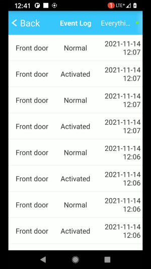
Event Log
The Event log can be found by going to your Home screen, selecting the More (…) link then selecting “Event Log“. Here, you can see everything that has happened on your system with the date and time it occurred.
Step 15 - System Maintenance
The last area to cover is the ongoing maintenance for your system. Since this is a Wireless system you will need to replace the sensor batteries on a regular basis. How long a sensor battery lasts will depend on the activity of the sensor. More activity means shorter battery life. As an example, a motion detector placed in your main hall way where there would be a lot of traffic would most certainly need battery replacement more frequently. The sensors in this system are equipped with a Low Battery feature which will alert you when a battery is low and needs replacement.

To replace batteries in the Door/Window sensor open the sensor by pressing on the tabs on the side and pulling open. Replace with a AA battery.

To replace batteries in the Motion Detectors use a small standard flat head screw driver or coin to pry open the sensor to expose the batteries. Replace with a AA Battery.

To replace the Hub batteries open the cover on the rear and replace with 4 AAA batteries
Specifications
| Manufacturer | Skylink |
|---|---|
| Product Dimensions | 38.74 x 10.16 x 12.7 cm; 589.67 Grams |
| Batteries | AA and AAA (not included) |
| Item model number | SK-200 |
| Colour | White |
| Power Source | 120VAC Adapter - 6VDC Output |
| Mounting Type | Surface Mount |
| Usage | Indoor use only |
| Included Components | Internet Hub HU-100 X 1, Door/Window Sensor WD-MT X 2, Motion sensor PS-MT X 1, Keychain Remote MK-MT X 1, Power Adapter X 1, Ethernet Cable X 1, Mounting Accessories |
| Warranty Description | 1 Year |
| Item Weight | 590 g |
Products Included in this Article
Tuya Wireless Alarm System Installation
Tuya Wi-Fi Alarm System Installation

In this article we will be covering the installation of the Tuya Wireless GSM Home Security Alarm System. You may find this system sold under different brand names but the system installation and setup would be the same for all. We purchased our test system from AliExpress.com
What you get
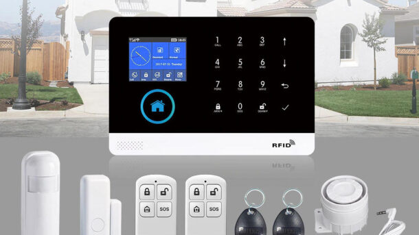
When purchasing this system you will need to choose from an array of kits/packages. The only difference would be quantity of sensors, fobs and remotes included. The actual devices would be exactly the same. A typical system would consist of a keypad/display, wireless door sensor(s), PIR motion detector(s), RFID Fobs, Remotes, and a siren.
Step 1- Keypad/Display Power Up
The first thing we need to do is setup the Keypad/Display. Connect the power adapter using the supplied USB cable into the Display’s USB micro connector on the side. Plug the adapter into a standard house wall receptacle.

Remove the battery tab (plastic tab) from the Display. This will connect the internal battery which will power the Display should there be a power outage. Next turn On the Display by pushing and holding the side Power Switch. At this point your Display should now be active and the LCD screen should display the default menu.
It defaults to English so if you want another language (total of 9 available) you can quickly change it by selecting the Down arrow(), select Settings() , x 3 until you get to Language then to select. Select the appropriate Language by using the key then . The Display should now be in your language of choice.

Step 2 - Installing the Smart Life App
To be able to receive notifications and control your system you will need the Smart Life App installed on your phone or device.
- Go to the App store on your phone and search for a App named Smart Life and select the Install button. In our example below we are using the Google Play Store.
- Accept the User Agreement and Privacy policy then select the Sign Up button.
- Fill in your Country and Email Address then select Get Verification Code. You will get a code sent to your email address. Enter the code into the Verification screen.

- Enter a Password then Select Done
- Enable or disable the Data Analysis option as you see fit. In my case I disable this option. Select the Go to App button. If you are prompted to allow Location permissions then go to your settings and turn on (allow) the Location Permission.
- You should now be in the Add Device screen


Step 3 - Adding the Alarm System to App
We now need to add your system to the App using your Wi-Fi network. Before beginning make sure your Phone/device is connected to same Wi-Fi network that will be used for the Alarm System.
- From the App’s Add Device screen select the Add Device button. Again, if you are prompted to allow Location permissions then select Settings -> Permissions -> Location -> Allow only while using app. Use the back key to return to App.
- From the Add Device screen select the option Sensors from the left menu.
- Next select Alarm (Wi-Fi) option from the sensor screen
- On the Wi-Fi screen enter the name (SSID) of your Wi-fi network. This needs to be a 2.4GHz network. This system will not work on 5GHz. Both your Phone and the Alarm system need to be on the same 2.4GHz network. Enter your network password and select Next

- At this point you may be presented with a “Reset the Device first” screen. This screen is intended for other types of devices that have a LED. Our system here has no such LED so simply select the Confirm option and select Next.
- An “Adding device…” screen will appear showing that it is scanning the network for the system. In about a minute it should detect your system and automatically add it to the App.
- When successful you will be presented with a screen stating the device was added successfully. It will also let you name the system. Go ahead and name it by selecting the Edit icon. Finally select Save then Done.

- A Notification Test message appears when security devices are added to the app on Android mobile phones. To ensure that notifications can be received, tap Test and follow the tips to verify that the autostart and battery usage detection permissions are granted to the app. You may not have these settings in your phone as it depends on your version and make. Newer versions do not require these settings. Select Next then Done
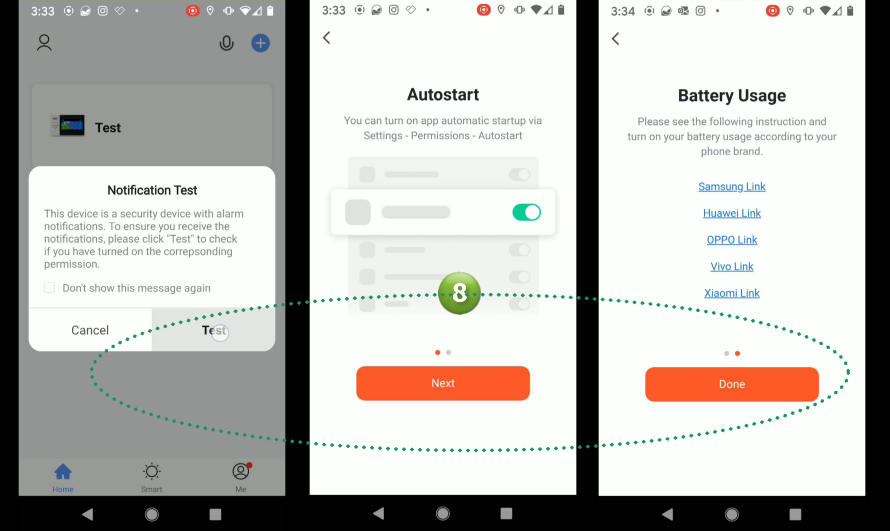
- The Alarm is now added to the Smart Life App and you should see your Alarm system in the Device list.
- To access your newly created alarm simply select it in the list. You should be presented with the Alarm’s main screen.

Step 4 - Enrolling Remotes

Key remotes allow you to Arm Away, Arm Stay, Disarm and generate an SOS. To add your remotes you need to be on the Main App screen.
- Select Accessories from the menu.
- Select Remote from Accessories then the Plus + to add
- At this point press and release the arm or disarm button on your remote while holding it near the display/keypad. The system should instantly read your remote and add it to the system.

- A Confirmation screen will be displayed. Select Confirm.
- To name your remote select it in the list and a editing screen will be displayed.
- Enter your name and select Save


Step 5 - Enrolling Sensors
We now need to tell the system what door/window/motion sensors you will be installing. This process is called enrolling. You can enroll sensors directly with the Display/keypad or by using the App. We will be using the App as it is a much easier process.
- From the App Main screen select Accessories.
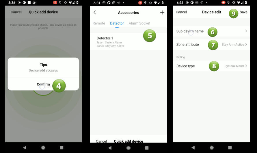
- From the Accessories screen select Detector then the Plus + to add
- The App will then search for your new sensor. Place sensor near Display and activate it. For a Door/Window sensor you can press the button or separate the magnet from the sensor. For a Motion sensor first turn it On by sliding the small switch on the rear of the sensor. Once activated the system will detect the sensor and will add it automatically to the system.

- A Confirmation screen will be displayed. Select Confirm.
- To name your sensor select it in the list and the Device edit screen will be displayed.
- Select Sub device name and enter your new name
- Select Zone attribute and select how you want this sensor to reactive when tripped. Refer to table below Zone Attributes.
- Select Device type and select the type that best describes this sensor i.e.: Door Alarm
- Select Save
Zone Attributes
| Out Arm Active | Active when you arm system in Away mode |
| 24 Hours Active | Active always – 24/hrs/day with siren |
| Close | Sensor is deactivated- will not cause an alarm |
| Door Bell | The sensor will act like a door bell and ring a chime (ding/dong) when tripped/activated. |
| 24 Hours Silent | Active always – 24 hrs/day but with no siren |
| Stay Arm Active without Delay | Active when you arm system in Stay mode and has no delay. Will instantly cause an alarm when tripped |
| Out Arm Active without Delay | Active when you arm system in Away mode and has no delay |
| Stay Arm Active | Active when you arm system in Stay mode |
Step 6 - Installing Wireless Door/Window Sensors

There are two parts of a wireless door sensor. A Magnet (smaller piece) and a Sensor. The Magnet is typically installed on the door or window itself while the Sensor is installed on the unmoveable frame. However, depending on your particular door/window you can reverse this as shown in the above image. Choose the best orientation for your situation while ensuring the gap between the Magnet and the Sensor is no more than 10mm or 1/4″. Important: Make sure the small triangle markings on each piece are lined up and facing each other. To install, remove the double sided tape backing from the magnet and Sensor and firmly place them on the door and frame. When done open the door/window to ensure the two pieces do not touch or rub. The Red LED should flash when you open the door/window. This signifies that a signal has been transmitted. Repeat these steps for all of your door/window sensors.
Step 7 - Installing Wireless Motion Detector

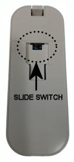
To install a Wireless Motion Detector first remove the detector section from the mounting bracket by holding the bracket then sliding the sensor up. Mount the bracket on the wall with the supplied screws and anchors if needed.
On the back of the sensor slide the ON/OFF switch to the ON position.
Placement of your motion detectors is important to ensure you get proper detection while avoiding false alarms. The following are some dos and don’ts when mounting your detector.
Don’ts
- Don’t point a detector at a window. Sun light will trip a PIR sensor.
- Don’t install this sensor where pets could enter the field of view (FOV). There are special detectors intended for use with pets.
- Don’t point at a hot air source like vents, heaters, air ducts, refrigerators or stoves
- Don’t mount pointing at ceiling fans or curtains
- Don’t mount detectors in a high humidity area like bathrooms and attics
Do’s
- Do mount between 6-8 feet (182cm-243cm) high from the ground/floor.
- Do mount sensor in a corner where possible. Corners tend to provide better coverage based on the pattern a detector senses
Step 8 - Mounting Keypad/Display
The Display/Keypad can be mounted on a wall or placed on a countertop or table using a stand like the Lamicall Adjustable Stand . Placing on a stand will allow you to somewhat hide the cables. On the other hand if you were to mount on a wall there would be cables running from the Keypad to the receptacle and siren that would be more visible. In any case both mounting types would work fine and would depend on your situation.
To mount on the wall first remove the mounting bracket from the back of the Keypad by sliding up. Mount the bracket using the screws and anchors provided. I would recommend using a level to ensure it’s straight. Slide the keypad back onto its mount and connect the power cable.
Mounting on stand is much easier. The Keypad comes with a built-in tamper switch on the rear of the Keypad. This is used to create an alarm should anyone remove the Keypad from the wall. You need to make sure the mounting bracket is installed into the rear of the Display. Then simply place the Keypad on the Stand and run you power cable to the closest receptacle.
Step 9 - Installing the Siren
The system comes with a hardwired siren that plugs into the side of the Keypad. However, it only comes with a short 3′ cable so you are limited on how far you can mount the Siren from the Keypad. Choose a suitable location and mount the siren using the screws provided then simply plugin the siren plug into the siren jack.
If you need to install the siren further from the Keypad you can purchase a 25′ extension cable.

Step 10 - GSM
We will not be covering GSM for this system. This version of the PG-103 only supports 2G which is no longer supported across Canada and the USA. If you purchase this particular version of the PG-103 then you will be able to monitor your system using the App only.
If you would like to have your system monitored over GSM then you should purchase systems that supports 4G or newer.
Step 11 - Settings
You can access the Settings screen from the menu in the Main screen.
| Exit Delay | When arming the system this is the amount of time in seconds the system will delay arming so you can exit the premise without tripping an alarm. Typical value would be 60 seconds. A count down beep will be heard during the exit period. |
|---|---|
| timer | The timer setting allows you to create timed events. For example, you could have the system Arm everyday at 10pm and/or Disarm everyday at 8am. Timer Events can be created for Disarming, Arming, Arm Home and SOS. |
| Arm Beep | When enabled/On every time you arm the system the siren will chirp to let you know the system armed. |
| Siren | When Enabled/On the siren will sound on any alarm. Disable/Off will turn the siren off. |
| Siren Duration | Setting this value to anything above zero will set the siren duration when activated. A typical setting would be 3 minutes meaning the siren will automatically turn off after 3 minutes of sounding. |
| Arm SMS | Arm SMS (Short Message Service) will have the system send you a text message when arming. Important: You must be using GSM (cellular) for this feature to work. This setting has no effect for this version of the PG-103 which does not support GSM or SMS. |
| Backlight | Turns the Display/Keypad LCD background light ON or OFF when not in use. |
| Alarm message propel | If disabled/Off then Alarm events will not be sent to your phone/device. alarm. When Enabled/On alarm notifications will be pushed to your phone/device. |
| Entry Delay | The amount of time (secs) the system will give you to disarm the system when tripping a Entry zone. |
| Alarm call unit | Allows you to add phone numbers when using GSM |
| Virtual password | Password used when communicating using GSM |
Step 12 - Testing your System
One of the most important steps when installing alarm systems is when you test the system. Even professional alarm technicians some times fail to perform proper and complete checks.
To test your system take your phone and test each sensor in all armed states of the system. This is to ensure that the sensor works and that you have set the Zone Attribute properly. Start with the system disarmed and proceed to the first sensor. Open the door/window or trip the motion detector. The red LED should flash on the sensor. Verify on the keypad that the intended result has occurred. Only 24 hour programmed sensors should cause an alarm at the keypad when disarmed. Next Arm the system and open the door/window or trip the motion. Again, verify the proper operation as intended. If the sensor is an Entry delayed sensor ensure you test the proper duration expires before an alarm occurs.
Repeat the above for each sensor installed while also verifying the proper zone/sensor descriptions are appearing on the keypad.
Next remove the Keypad/Display power adapter from the receptacle and ensure your system remains operational. You should be able to arm and disarm the system as normal. Replace the adapter and verify no change on your Keypad/Display.
You should now have a fully installed and functional system.
IMPORTANT: You must continually check your sensors for proper operation to ensure the batteries still have a enough energy to be able to send a signal to your keypad/display. This system does not have the capability to monitor your sensor batteries and notify you of troubles. This means a sensor could stop working or be removed entirely and you would be unaware. You will need continually test your system to ensure all sensors are functioning.
Step 13 - System Maintenance
The last area to cover is the ongoing maintenance for your system. Since this is a Wireless system you will need to replace the sensor batteries on a regular basis. How long a sensor battery lasts will depend on the activity of the sensor. More activity means shorter battery life. As an example, a motion detector placed in your main hall way where there would be a lot of traffic would most certainly need battery replacement more frequently.
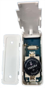
To replace batteries in the Door Sensors just slide off the cover to expose the battery compartment. Replace the battery with a CR2032 Battery.

To replace batteries in the Motion Detectors first remove from its mounting bracket. Use a small standard flat head screw driver to pry open the sensor to expose the batteries. Replace the batteries with two AA Batteries.

The Remote can be opened with a small flat head screwdriver. Insert into the small opening along the side and pry open. Replace with a CR2032 Battery.

The RFID tags do not have batteries

The Display also contains batteries but I don’t believe the manufacture intended the end user to replace them. Opening the display runs the risk of damaging the display. However, if you are willing to take the risk then you can open the case by removing the two rubber plugs that hide the screws keeping the display together. One plug is on the side above the Siren jack and the other is on the back center. Once the screws are removed you can carefully pry open the display to expose two batteries. The 1000ma 3.7 V (in mine part# WZY 523450) rechargeable battery used to provide backup power during power failures and the CR 1220 that I would assume is for the clock and/or memory.
WARNING! Opening the display may result in damage and most certainly would void any warranty you may have. Open only if the display has become a brick.
Products Included in this Article
- Lamicall Adjustable Tablet Stand Holder - Foldable Desktop Stand Charging Dock for Desk Compatible with iPad Air Mini Pro 9.7,12.9, Phone 12 Mini 11 XS Max XR X Plus S10 S9 S8 Smartphones 4-13” - GrayUL Listed Extra Long 6.5 Ft AC Adapter 2.1A Rapid Charger for Fast Charging Hd Hdx 6" 7" 8.9" 9.7" Tablet and Phone Tab Power Supply Cord
Other Products you may be Interested in
Security Glossary of Terms
Security Glossary of Terms
To help you get a handle on Security vocabulary and the associated jargon, we’ve compiled this comprehensive glossary with definitions, helpful links and images.Menu2.4G Wireless
2.4G is short for the 2.4GHz radio frequency band used in Wi-Fi routers. The 2.4G band will provide longer range than the newer 5G band but cannot handle the same amount of bandwidth (channels) as 5G. It also is more likely to be affected by external interference like devices using Bluetooth, ZigBee, and cordless phones .
5G Wireless
5G is short for the 5GHz radio frequency band used in Wi-Fi routers. The 5G band has higher bandwidth (more channels) than the older 2G band so it can provide much faster downloads, uploads and video streaming. However, it's range (distance coverage) is less than the 2G bands (almost 50% less).
Ampere Hours (Ah)
An Ampere Hour or amp hour (Ah) for short is a unit of electric charge. In simpler terms its the number of amps (current) a battery will provide per hour. One AH would be 1 Amp for one hour. In the security world its used to describe the backup capacity of a system. To use an alarm system as an example. If your alarm uses a continuous one (1 ) amp of current in normal operation, there is a 7Ah battery installed in the Control Panel and there's a power outage. The alarm will continue to operate for approx. 7 hours.

Backup Battery
Typically placed inside in the Control Panel and is used to provide power to the system during a power outage. They are rechargeable so once the power has been restored the control panel will replenish its charge. Batteries come in many different sizes and are measured in Ampere Hours (Ah). Typical battery life would be approx. 3-5 years but some have been known to reach 10+ years. Checking these batteries should be part of a regular maintenance routine.

Burglar Alarm System
An electronic system consisting of a Control Panel/HUB, detection sensors and Keypads and or Touch screens. Systems can activate sirens and/or strobes and be monitored remotely. Used to detect unauthorized entry into a premise.
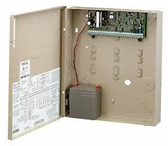
Control Panel
A Control Panel is considered the brains of an alarm system. It will typically will take the form of a small metal enclosure that houses an electronic circuit board inside. This is where you would wire in sensors (if a hardwired system), connect keypads, install the backup battery and connect to household power. Optional or specialized circuit boards are also installed inside this control panel. It will in many cases have a lock on the door to prevent unauthorised entry.
Cellular Monitoring
Alarm Systems that use Cellular Monitoring means that it is using a digital cellular network to send alarm, trouble and supervisory messages to a remote Monitoring Station system. The system uses a cellular communicator normally inside the control panel to send signals.

FOV
FOV stands for Field of View. This term is used in multiple areas in security. For Motion Sensors it describes the area that a Motion can detect movement. For Cameras it's the area that can be seen by the camera.
Frames per Second (FPS)
The frame rate measured in Frames per second. This is the rate at which images are captured or displayed. Used with video cameras to describe how many frames (images) are being captured per second. A video camera set to 30FPS means it is capturing the image/scene at 30 images per second.
GPRS - General Packet Radio Service
A data packet oriented data standard used on the 2G and 3G cellular communications networks. It is an enhancement to the standard GSM network infrastructure. It provides for moderate speed data transfer. 2G is almost all but phased out (service no longer available) and 3G is is in the process of being phased out by the major carriers.
GSM
The Global System for Mobile (GSM) is a international standard that defines the protocols used with digital cellular networks . It is a 2nd generation technology (2G) and is almost all but phased out (service no longer available) in US and Canada. GSM was a digital cellular technology used to transmit data and voice communications at a frequency range between 850MHZ and 1900MHZ.
Hardwired System
A Burglar Alarm system that uses wires and cables to connect it's devices to the main Control Panel.

Mesh Network
A mesh network allows each device in a network to operate as a repeater and pass the signal on to another device. This causes mesh networks to be more versatile. They cover greater distances and can even work around obstacles.
Mesh Hop
A wireless mesh network is a network where the nodes in the network communicate with other nodes to achieve increased coverage and connectivity by forwarding messages on behalf of others.

Monitoring Station (MS)
Monitoring Stations or Centers are facilities that monitor alarms, troubles and supervisory events from security systems. When an event is received by a MS trained operator they will dispatch the appropriate authorities and/or depending on the event contact the customers representative (pass card holders). Monitoring Stations run 24 hours a day and provide all the automated computer systems to be able to handle 1000's of alarm per day. Depending on what type of monitoring is being provided a MS may be listed with organizations such as UL, ULC. If listed it means that they have demonstrated compliance to the strict monitoring station requirements of theses organizations. Ongoing audits are conducted by these organizations to ensure ongoing compliance.
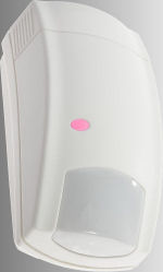
Motion Detector/Sensor
Motion Detectors are also called Motion Sensors or just plain Motions. It is a device that detects movement of objects in it's field of view (FOV). They come in many shapes and can use different technologies to actually sense movement. The most common type of Motion is a Passive Infrared Sensor (PIR). It uses an electronic sensor inside that measures the amount of infrared (IR) light coming from a object. It also uses electronics inside to determine if the amount and type of movement is enough to trip the sensor. Other technologies used include Microwave and in the old days Ultrasonic. Nowadays Ultrasonic detectors have been replace with PIR but is still used in may other industries.

IP Camera
IP (Internet Protocol) Camera refers to digital cameras that transmit their video over a IP based network. They are typically connected using a standard Ethernet cable (cat5 or cat6). They can also use Wi-Fi instead of a hardwired connection to transmit it's video. IP Cameras typically provide higher resolution video as compared to their Analogue counterpart. The power needed to operate an IP Camera could be provided using POE (Power Over Ethernet) or separate power cables. However, in order to use POE both the camera and the network device (router) its connected too must support POE.
IR
IR stands for Infrared radiation. It is a type of radiant energy that's invisible to human eyes. All objects radiate some amount of IR but Humans and animals radiate a good amount. That's why PIR's use IR technology to detect people. It is sometimes referred to as the Heat being radiated from a human body.
PIR
PIR stands for Passive Infrared. It is a type of sensing technology used in Motion Sensors that detects movement using the Infrared Energy (IR) being radiated from an object. See Motion Detector/Sensor.
POE - Power Over Ethernet
POE is a technology that allows the powering of network devices, like IP cameras, over the same network cable used to send/receive network communications for the device. In the security industry this is used mostly when using IP Cameras but can also be used with other devices.
RFID
Radio Frequency Identification (RFID) is a technology that allows the storage of digital data inside a Tag, Key Fob or Card which can then be captured by a reader using radio waves. RFID devices are typically made of durable plastic and contain an integrated circuit and an antenna. There are Active Tags and Passive Tags. Active Tags have built-in power (battery) while Passive Tags are powered-up by the RFID reader. When a Passive Tag is presented to a RFID reader they receive power (from the reader) and in turn will transmit the data contained inside.

SIM Card
SIM stands for Subscriber Identity Module. A SIM Card is basically a integrated circuit running a Card Operating System (COS) Operating system. It stores the identity of a subscriber and is used to authenticate on a mobile phones, satellite phones, smart watches, computers and other devices. It also stores carrier specific information. There are three different types of SIM's. Standard, Micro and Nano. Both the Standard and Micro are rarely used these days. Nano SIM cards are by far the most widely used.
Streaming
The act of transmitting video and audio files (media) continuously over a wired or wireless network. It is a delivery method not the content.
ULC - Underwriters Laboratories of Canada
Underwriters Laboratories of Canada (ULC) is an independent product safety testing, certification and inspection organization. They accredited by the Standards Council of Canada. ULC set requirements for Monitoring Stations
Wireless System
A Burglar Alarm system that does not use wires and cables to connect it's devices to the main Control Panel. Devices communicate to the Control Panel using Radio Frequency (RF).
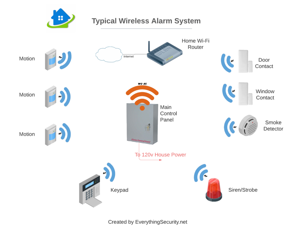
Wireless Vs. Hardwired Alarm System. Which is best?
Alarm Systems are installed to safeguard your home and your family, so it is always paramount to install one that will be reliable. Basically, alarm systems come in three configurations: Wireless, Hardwired and a hybrid of both. It’s important to understand the benefits and disadvantages of each to help you make an informed decision when choosing the right alarm system for your home.
Each homeowner will want something different based on their situation and why they need the alarm. So in the rest of this article, I’ll go over all the different configurations while highlighting their pros and cons.
Wireless Systems

Historically wireless alarm systems had a bad reputation as they where not as reliable. In Fact, I remember when my first wireless system was installed. It was new technology back then and we were constantly returning to adjust/reconfigure trying to make the system more reliable. We have come a long way since then and can now consider a wireless system as reliable as their hardwired counterpart.
In a wireless system, the doors and windows will have wireless sensors that transmit their status (open/closed) to the main control panel using Radio Frequency (RF). Sensors like water detectors, smoke detectors, glass breaks and others can also be installed and would transmit their status to the main control panel as well using RF. There are some limits on the number of wireless sensors that can be assigned to a control panel. The actual number will vary based on the brand/model of the Panel you use. You will need to ensure that your panel can handle the number of sensors you plan to install. This is usually not a problem for most homes/businesses as typical systems could handle anywhere from 8 to over a hundred wireless sensors.
Keypads and/or Touch Screens are used to control your alarm system and are typically installed at your entry/exit points to allow quick access when leaving or entering the premise. These keypads can use RF to wirelessly transmit your commands (Turn On/Off) and receive status signals like windows/doors opened.
Wireless Sirens/Strobes can also be added to a wireless system. When an alarm event occurs the Control Panel will activate the siren/strobe by sending a RF signal to it.
The Control Panel needs to be connected to your regular household power. This would normally take the form of a small adapter/transformer that would plug into a receptacle then wired to the panel. This powers your system and charges the stand-by battery located inside the control panel.
To be able to send messages/data outside your home to services like monitoring stations and/or a smart phone apps the Control Panel can be connected to the Internet through your home Wi-Fi router.
Wireless systems can also be connected remotely by using a standard Cellular network. A SIM card would be installed into the control panel just like a regular cell phone. It is not mandatory to use a cellular connection but is usually included in a professionally installed system that is connected to a monitoring service. Using cellular connection would provide for a better level of security but is not required if you plan on doing it yourself (DIY) and want to do your own monitoring.
Tip - Systems without Cellular While your alarm system has a back-up power source and will keep working in a power outage, your home Wi-Fi router usually does not. Without battery backup for your home Internet Wi-Fi router your smart phone app will lose its connection to your alarm system until power is restored. This would mean no messages can be sent to your smart phone app. However, there are solutions available that can be added that will provide backup power to your Wi-Fi router. Some routers have an option to have a backup battery installed but you would normally need to request this optionSignal Interference
When working optimally, the Radio Frequency (RF) of a wireless system should be able to travel through walls and floors. However, there is always a chance that the signal will not reach its destination/sensor or that another signal may interfere with it. The number of walls and the construction type will also affect the signal reach. Signal quality will also differ depending on the system type/model used so what may work with one system may not work on another.
If you have a large home, this could leave some areas unprotected. In addition, wireless alarms are more susceptible to false alarms if they are not installed correctly or if there is interference from other devices.
Batteries
One of the most important differences to consider is how the two systems use batteries.
Wireless devices such as door sensors, motion detectors, water sensors, smoke alarms and others are usually powered by a small 3v lithium battery. Life expectancy for these batteries is typically 1 to 3 years. How often a motion is tripped or a door is opened (transmits a signal) will determine the actual life span.
A Wireless system would typically have a larger backup battery installed in the Control Panel (7AH or more for you techies) . This battery is continuously charged by the regular household power. It is generally only used when you have a power outage. It will keep your Control panel and any connected devices working for many hours. Of course, a power outage would not affect your wireless sensors as they have their own batteries and do not receive power from the control panel.
An important thing to consider when choosing between a hardwired and wireless system is the maintenance required for the wireless sensor batteries. You will need to go to every device/sensor to replace the battery every 1-3 years. At the time of writing this article a set of 4 standard CR2032 batteries costs approximately $10. For CR 123A batteries the cost is around $23 for a package of 4. However, the type and cost for batteries will depend on the type of system.
The Pros and Cons of a Wireless System
Below are the Pros vs Cons of a typical Wireless System as compared to a Hardwired system
Pros
- Easy Installation
- Cost Effective
- Scalable - Adding/Changing is easier
Cons
- Battery replacement every 1-3 years
- More susceptible to RF interference
- Limited range for sensors
Hardwired System
In a Hardwired system all devices would be connected to the Control Panel using cables (hardwired). Devices would include Door Contacts, Window Contacts, Motion Detectors, Water Sensors, Smoke Detectors and many more. Hardwired systems are perfect for when you have access to inside your walls like when you are doing renovations.
There are limits on the number of sensors that can be connected to a given control panel which varies based on the brand/model of the Control Panel you use. The number of zones will determine the number of sensors. Now, some of you who may be familiar with alarm systems may say that there is no limit as you can connect multiple sensors to any given zone. While you would be correct I would highly recommend that you place a single device per zone for identification purposes. Should you have a false alarm (alarm tripped) from a sensor that is connected to a zone that has multiple sensors connected then it would be impossible to tell which sensor actually tripped the alarm.
While the sensors/sirens/strobes would be installed using wire/cables the main control panel would still use some wireless communications. This could be in the form of cellular and/or Wi-Fi depending on your particular setup. Cellular networks when connected to a monitoring service and/or Wi-Fi when connecting to your Wi-Fi router. Both methods would allow for smart phone app access to your system.

The Pros and Cons of a Hardwired System
Below are the Pros vs Cons of a typical Hardwired System as compared to a Wireless system
Pros
- No ongoing sensor battery replacement
- Less susceptible to RF interference
- Larger range for sensors
- Less electronics mean less possible failures
Cons
- Sensors limited by the number of zones available
- More difficult to make changes if needed
- More expensive due to installation costs*
*Note: Professionally installed systems are typically lower cost when a locked in contract is offered.
Hybrid System
In a Hybrid system you get the best from both Wireless and Hardwired devices. These systems allow you to use wireless sensors and hardwired sensors together in one system. It is more common to find Hybrid systems when using a professional grade system but can be found in the DIY level systems as well.
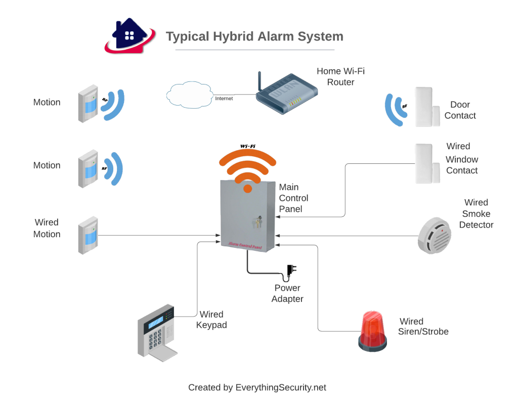
The Pros and Cons of a Hybrid System
Below are the Pros vs Cons of a typical Hybrid Alarm System.
Pros
- Allows you to connect sensors farther from the panel where Wireless may not reach
- Allows connection of devices not available as Wireless
- Less maintenance (Less Batteries)
Cons
- Still has Wireless sensors that will require higher maintenance (battery replacement)
- Wired portions will require cables to be run
- More expensive due to having both Hardwired and Wireless connections
*Note: Professionally installed systems are typically lower cost when a locked in contract is offered.
Summary
Deciding between a hardwired, wireless and Hybrid system can be a difficult decision. The three main things to consider is who will be installing (DIY or professional installer), where you plan to install it and your budget. If you are technically inclined and like doing it yourself then a Wireless System would probably be your best choice. However, if you have more advanced skills then tackling a Hardwired or Hybrid system is not out of the question. Especially if your home/business is currently under construction and you have access to inside your walls.
Of course if your budget can handle it, then having a professional installer do the work will save you a lot of time and work.
My recommendation? Well if I would be installing a system I would likely go with the Hybrid system just so that I’m covered in case there are issues with Wireless sensor range. This way I can run a wire if needed.
No matter which direction you go you can always rely on EverythingSecurity.net to help you along the way. Please feel free to Ask Us any questions you may have. We would love to hear from you.
Products Included in this Article


